
[ad_1]
Sponsored by Littelfuse.
The automotive atmosphere is among the most extreme environments for electronics. As we speak’s automobile designs proliferate with delicate electronics, together with digital controls, infotainment, sensing, battery packs, battery administration, electrical automobile powertrains, and on-board chargers. Along with the warmth, voltage transients, and electromagnetic interference (EMI) within the automotive atmosphere, the on-board charger should interface with the AC energy grid, requiring safety from AC line disturbances for dependable operation.
As we speak’s element producers provide a number of gadgets for safeguarding digital circuits. Because of the connection to the grid, on-board charger safety from voltage surges utilizing distinctive elements is crucial.
Littelfuse options deal with superior overcurrent and overvoltage safety applied sciences, together with MOV (Steel Oxide Varistor), TVS (Transient Voltage Suppressor), GDT (Gasoline Discharge Tube), and SIDACtor® safety thyristors. The problem for design engineers? The right way to optimize the element choice and decide one of the best mixture of applied sciences to succeed in one of the best efficiency and worth.
A novel answer combines a SIDACtor and a Varistor (SMD or THT), reaching a low clamping voltage beneath a excessive surge pulse. The SIDACtor+MOV mixture permits automotive engineers to optimize the choice and, subsequently, the price of the ability semiconductors within the design. These elements are wanted to transform the AC voltage into the DC voltage to cost the automobile’s on-board battery.
The On-Board Charger (OBC) is in danger throughout EV charging as a result of publicity to overvoltage occasions that will happen on the ability grid. The design should shield the ability semiconductors from overvoltage transients as a result of voltages above their most limits can harm them. To increase the EV’s reliability and lifelong, engineers should tackle growing surge present necessities and decrease most clamping voltage of their designs.
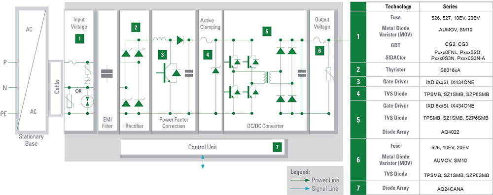
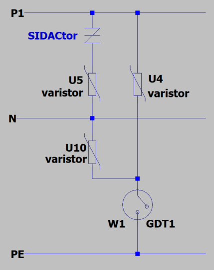
Determine 1 exhibits the circuits requiring safety elements and blocks that may make use of high-efficiency elements. The desk lists the advisable applied sciences.
The potential surge pulses for the OBC come from oblique lightning strikes, load switching, and failure within the system. Think about the ability of a direct lightning strike of 100kA; a excessive surge present requirement within the specification is comprehensible. Different potential root causes for a surge pulse are abrupt load switching and faults within the energy system.
Instance sources of transient voltage surges embody the next:
- Switching of capacitive hundreds
- Switching of low voltage programs and resonant circuits
- Quick circuits ensuing from building, visitors accidents, or storms
- Triggered fuses and overvoltage safety.
The coupling of the surge pulses is capacitive on parallel cables, inductive on conductor loops, and emission within the close to area. The transient surge happens over cable (on energy, information, or sign traces), and it may be symmetrical (line-to-line) or asymmetrical (line-to-ground). It’s essential to know the coupling and propagation supply to unravel the applying downside.
The IEC-61000-4-5 is the related normal for surge immunity. Desk 1 lists most surge voltages as much as 4kV. The 2Ω generator resistance ends in a 2kA surge pulse (1a). The IEEE C62.41.2-2002 normal specifies a 6 kV/3 kA surge ranking (1b). As we speak, most energy grid-related AC energy circuits are designed to withstand the IEEE surge requirement.
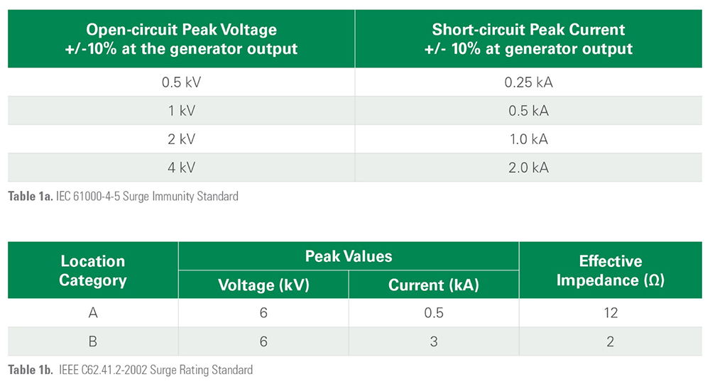
IEEE C62.41.2-2002 Commonplace 1.2/50 µs-8/20 µs, anticipated voltages and present surges.
In accordance with the 6kV/3kA surge, many designers use 14mm MOVs within the AC major aspect circuit.
A 20mm MOV is most popular for higher reliability and safety. The 20mm MOV handles 45 pulses of 6kV/3kA surge present, which is far more strong than the 14mm MOV. The 14mm disc can solely deal with round 14 surges over its lifetime.
Voltage transient safety efficiency comparability
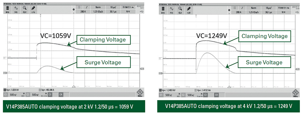
Examine an MOV’s transient voltage safety efficiency with a SIDACtor+MOV mixture. Determine 3 exhibits the clamping efficiency of a 14mm MOV when struck with a 2kV and a 4kV surge. The MOV has a most working voltage of 385VACRMS. The clamping voltages are greater than 1000V, which places a excessive stress stage on the ability semiconductors.
MOV transient voltage efficiency
MOV Choice Parameters
- Rated Working Voltage—Most steady voltage of the circuit to be protected.
- Ambient Temperature—Temperature within the space surrounding the MOV, used to find out if thermal derating is required.
- Transient Voltage Waveform—Defines the transient pulse, together with peak voltage, length, and transient supply impedance, usually supplied in a Commonplace (e.g., IEC-61000-4-5).
- Amount of Transient Voltage Pulses—Outlined by the Commonplace, that is the variety of pulses that the elements should survive, and that the MOV might want to soak up.
- Peak Pulse Present–Transient voltage pulse and the generator’s inner resistance present the height present.
- Mounting necessities of MOV (straight, bent leads or SMD).
- Requirement to satisfy the 6kV/3kA waveform drives MOV choice. The standard lifetime requirement is 10 pulses.
Instance choice dedication
Stage 1 Charger—120VAC, single-phase circuit: The anticipated ambient temperature is 100°C.
Step 1: Decide the minimal voltage ranking of the MOV. The rule of thumb is so as to add 25% to the nominal AC line voltage to account for an imperfect energy service: 120VAC x 1.25 = 150VAC. That is the minimal recommended voltage ranking. The utmost peak surge present should be above 3kA.
Step 2: Repetitive Surge Functionality should meet the usual necessities. The height surge present and the power ranking should be lowered based mostly on the temperature derating chart. The excessive potential capability relies on the coating choice. Utilizing a GDT helps the safety configuration obtain the leakage necessities of the Excessive Potential take a look at, which an MOV can’t meet alone.
SIDACtor+MOV transient voltage efficiency
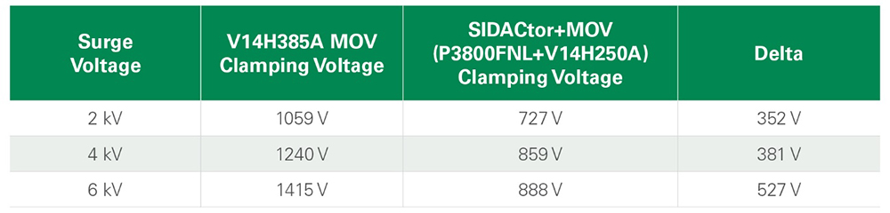
The SIDACtor+MOV strategy has a number of benefits. The first profit is that for a 6KV/3KA surge, the clamping voltage is beneath 1000V as indicated in Desk 2.
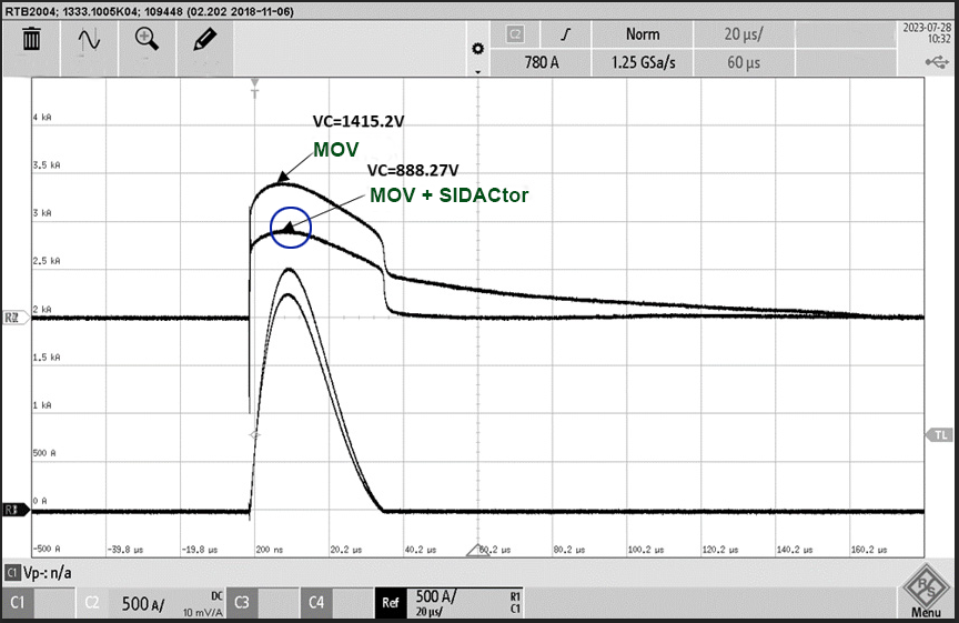
Determine 5 illustrates the voltage versus time response of the MOV and SIDACtor+MOV mixture, once more displaying that the SIDACtor+MOV mixture has a decrease clamping voltage.
An MOV alone exhibits degeneration after a number of surges. The leakage present will increase with the variety of surges the MOV should soak up. Additionally, the breakdown voltage is predicted to fall with an growing variety of surge strikes. The rising leakage and the clamping voltage change present the MOV parameters’ drift. Designer ought to choose a bigger disc measurement to keep away from this case with an MOV. This strategy impacts the fee and consumes crucial PCB house. Nonetheless, their efficiency is extra steady with a SIDACtor+MOV mixture, and the SIDACtor extends the MOV lifetime.
SIDACtor+MOV: The superior answer for transient surge safety
Whereas a designer will think about an MOV for voltage transient safety of downstream circuitry, Littelfuse can provide the designer a superior answer with its SIDACtor safety thyristor positioned in collection with an MOV. The SIDACtor+MOV mixture has a decrease clamping voltage to cut back semiconductor stress. As well as, the mix has a a lot decrease leakage present and a breakdown voltage that degrades a lot much less with growing transient strikes. Utilizing a SIDACtor+MOV mixture for transient surge safety will end in a extra dependable, strong on-board charger.
To be taught extra about utilizing SIDACtor Safety Thyristors in electrical automobiles, obtain the The right way to Choose the Optimum Transient Surge Safety for EV On-Board Chargers software observe, courtesy of Littelfuse, Inc.
Be taught extra:

[ad_2]